my original tower project was based on a five 5-1/4" external bays, two 3-1/2" external bays, and two 3-1/2" internal bays case for an AT style motherboard. the a2000 motherboard necessitated a reduction to three 5-1/4" external bays. the remainder of bays stayed unscaythed.
ok, you've got an a2000 within which you'd like to install a cd-rom, harddrives, a couple of floppy drives, maybe a tape drive.....and still have room to add an extra device or two. neither desktop case will accommodate such expansion. (sure, external cases are an option; however, this is about practicality and "oneness.")
what to do?
well, are you relatively handy with a soldering iron? with tin snips? do you have a saber or hack saw? file? are you confident? if you are, and have the inclination, here's how i moved my a2000 motherboard from a single story ranch to a sky-scraper dwelling. i am not placing all the details within, because you'll have different ideas as to what modifications to make (extra db-9 connector mountings, etc.). and i'm assuming that if you're tackling this project, i don't have to spell out the details (e.g., how exactly to make the switch connections within the power supply or what soldering/desoldering tools to use).
currently, the write-up assumes that you can "fill in the details" for many of the mechanical and electrical modifications. furthermore, there are only a few pictures of the tower at the bottom of this page. no close-ups of the internals or motherboard modifications. as time permits, i'll add more pictures, diagrams, and details.
the amiga motherboard is a monster. even compared to the old full-sized 286 motherboards of yesteryear. yup, mounting the motherboard on the pc case would be the challenge! what to do? i thought about it for a few minutes and then it struck me: take the a2000 chassis and mount it in the tower! after all, what's a little more metal work?
here's what you need to do:
by far this is the most critical and sensitive portion of the modification. if you're not prepared (or capable) to de-solder the connectors on the motherboard, DON'T! find someone who can. getting the old solder to re-flow is difficult and may cause you to ruin your motherboard by lifting and burning traces! to ease the process, use a bit of fresh solder to re-flow the old solder.
the mods that need to be made are:
the above two are done as they are to allow you to remove the motherboard as easily as possible.
one of the things that always irked me about the a2000 power supply was that the harness exited the power supply from the side adjacent to the accelerator slot. this bundle just made installation of the accelerator more difficult than it had to be; furthermore, the harness exerted too much pressure (imo) on the gvp simms and impeded air flow over them. since the case must have the power switch on the front, i figured that as long as the power supply has to be opened, i may as well drill a hole on the power supply case for the harness to exit at a "better" location: i drilled a 1 1/8" hole on the sloped face of the power supply and pushed the connectors though it. i drilled a small hole for the power switch leads and made the appropriate modifications. remember to use plastic or rubber grommets to protect the wires as the exit the power supply!
a caution: it's unfortunate, however this is not the most rigid case. specifically, when installing boards make sure that you place one hand on the backside of the a2000 chassis to provide equal pressure to that exerted when seating the boards in the slots. this will keep you from flexing the mated-chassis surfaces. or, better to just lay it down on its side to install hardware. this summer i'll probably reinforce the case by placing small metal dowels behind the a2000 chassis.
i don't know where i got these, but i had a couple of small amiga plates/logos that were in my desk drawer. hey, what's a girlfriend if not a little vain and deserving of a couple of nice accessories?
i wish my nephew (3 years old now) would have been as wise as he is now. if only he would have told me "take your time, uncle greg!" as he does now, the case would have been better planned and constructed. (it's just a tad out-of-square: i hate that! "dammit, man, i'm a woodworker, not metalworker!") but it's solid....who knows, phase two may be in the works. as will a better and more detailed "how-to" web page!!!!
i hope this helped.
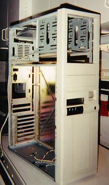
above is a 3/4 front view of the nearly completed structure. note that the original chassis is inserted within the tower case, and that the original 5.25" external bays are reduced in number by two.
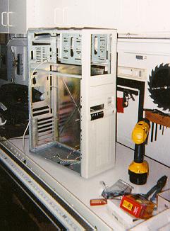
just another 3/4 front view from a slightly different perspective.
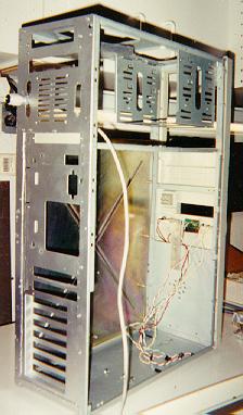
above is a 3/4 rear view. note that at the top of the rear panel is an access hole for the internally mounted clarity 16 (which rests on the aluminum deck riveted to the back panel). the slot just below that is the mounting hole for the 8-port hub. these, along with the extra fan mount, will be replaced by an additional power supply and internal 3.5" harddrive bay at the rear of the tower. also, on either side of the fan are openings for db-25 and db-9 connectors.
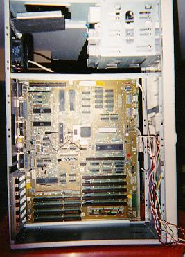
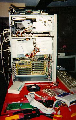
the above picture shows the motherboard mounted within its new accomodations. tough to see, but notice the dangling keyboard extension just in front of the kick start rom. i'll get some close-ups of the motherboard.
questions, comments, concerns? e-mail me.
This site developed and maintained by greg kimnach.
"Do or do not. There is no 'try'."
--Yoda, Jedi Master